Electronic and Hardware Setup for GPIO and Seven Segment Display
GPIO
This Readme talks about basic electronic setup for LED on Jetson Nano
GPIO Hardware
- 1 Qty 5mm red LED
- 1 Qty P2N2222 Transistor
- 1 Qty 330Ω resistor
- 1 Qty 10kΩ resistor
- Hookup wire
- Breakboard
GPIO Setup
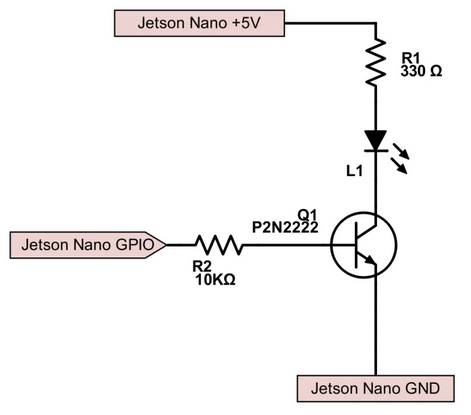
GPIO Electronic Wiring
The Collector, Base, and Emitter are different depending on which part number you have. We’re using a P2N2222 here. We will be wiring the red wire to +5V on Pin 2 on the Jetson, the black wire to GND on pin 6, and the transistor Base through the base resistor on Pin 12.
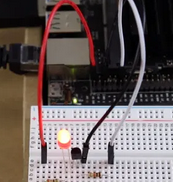
GPIO Result
Seven Segment Display
Seven Segment Display Hardware
- 1 Qty 4 Character 7 Segment LED made by Adafruit
- Hookup wire
- Breakboard
Seven Segment Electronic Wiring
- GND J3A1-14 -> LED Backpack (GND)
- VCC J3A1-1 -> LED Backpack (VCC – 5V)
- SCL J3A1-18 -> LED Backpack (SCL)
- SDA J3A1-20 -> LED Backpack (SDA)